Monday, July 13, 2015

Temperature Meter using Microcontroller and LM35 Temperature Sensor


Temperature Meter using  Microcontroller and  LM35 Temperature Sensor
We can  build a Temperature meter by pic18f2550 microcontroller and we need a temperature sensor . In this project we will use LM35 temperature sensor and it is a popular temperature sensor .Look at the picture which is given below .
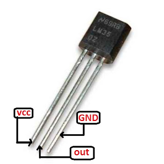
Microcontroller Project : Temperature Meter using  LM35 Temperature Sensor and pic18f2550 Microcontroller
The Picture has been taken from internet
LM35 produce different voltage outputs at different temperatures . LM35 increase it's output voltage 10mV or 0.01v  for each degree increment of temperature . That means 0.01 v per degree centigrade. 
Now we need to get a microcontroller as a system to read temperature from sensor . We will use ADC of the microcontroller and the reading will be shown in LCD display . It's the basic idea of the project .

We need a basic knowledge about ADC . Let's  take a look at here :

Thief Detector using PIC Microcontroller & PIR Motion Sensor

Thief Detector using PIC Microcontroller & PIR Motion Sensor
ADCON1 Register
Basically ADC is like as voltage divider . According to voltage It produce output .
bit 5 : VCFG0: Voltage Reference Configuration bit (VREF- source)
1 = VREF- (AN2)
0 = VSS or 0 volt


bit 4 :VCFG0: Voltage Reference Configuration bit (VREF+ source)
1 = VREF+ (AN3)
0 = VDD or 5volt


We will set  VCFG0[bit 5]=0and VCFG0[bit4]=0 . So we will get highest value 5volt[1023] and lowest value 0volt[0].The ADCON1 is a 10 bit register that means  (2 to the power 10) is it's highest counting capacity and the result is 1024 . So this register can count from 0 to 1023 . When 0 volt , we get reading at RA0 pin  0 .When 5 volt , we get reading at RA0 pin 1023. It means 5volt equivalent to 1023 .
 If  1023 reading value    equal   to 5 volt.
So 1      reading value    equal   to  5/1023 volt
So 'read_val'  reading  value   equal  to (5/1023)*read_val .volt .
As we know LM35 reading can be changed  with  0.01 v per degree centigrade change . According to the datasheet 10mV = 1 degree centigrade temperature .The temperature calculation should be like that :
    0.01 volt   for     1      degree centigrade Temperature
so  1     ,,       ,,  (1/0.01)   ,,         ,,              ,,
and (5/1023)*read_val    volt    for  [{(5/1023)*read_val }/0.01]  degree centigrade Temperature .

Source Code :


sbit LCD_RS at LATB7_bit;
sbit LCD_EN at LATB6_bit;
sbit LCD_D4 at LATB5_bit;
sbit LCD_D5 at LATB4_bit;
sbit LCD_D6 at LATB3_bit;
sbit LCD_D7 at LATB2_bit;

sbit LCD_RS_Direction at TRISB7_bit;
sbit LCD_EN_Direction at TRISB6_bit;
sbit LCD_D4_Direction at TRISB5_bit;
sbit LCD_D5_Direction at TRISB4_bit;
sbit LCD_D6_Direction at TRISB3_bit;
sbit LCD_D7_Direction at TRISB2_bit;
// End LCD module connections

double source=0;
int temperature=0;
char txt[15];

void main() {
ADCON1=0x0E;                  // Configure RA0 pin as input
CMCON=7;
TRISB.F0=0;
  ADC_Init();                        // Initialize ADC

  Lcd_Init();                        // Initialize LCD
  Lcd_Cmd(_LCD_CLEAR);               // Clear display
  Lcd_Cmd(_LCD_CURSOR_OFF);          // Cursor off

  Lcd_Out(1, 3, "Temperature");
                  // Different LCD displays have different
  Lcd_Chr(2,12,223);                   //   char code for degree
  Lcd_Chr(2,13,'C');                  // Display "C" for Celsius
  while(1){
 source=Adc_Read(0);
 source=(source*5)/1023;
 source=source/0.01;
if(source>30){       // when temperature goes higher than 30 degree , fan turns on .
PORTB.F0=1;
} 
else{                    // when temperature goes lower than 30 degree , fan remains off .
 PORTB.F0=0;
}
inttostr(source,txt);
Lcd_Out(2,1,txt);


}
}

Circuit :

Temperature Meter using  Microcontroller and  LM35 Temperature Sensor


During temperature lower than 30 degree:

Temperature Meter using  Microcontroller and  LM35 Temperature Sensor


During temperature higher than 30 degree:

Temperature Meter using  Microcontroller and  LM35 Temperature Sensor

This Project's Proteus Simulation in Youtube , Please Watch This:


Simply Just click on the "Skip Ad" and you will get the download option.

Thank You !!


Saturday, July 11, 2015

Water Level Indicator Project using Microcontroller


Water tank controller  is an embedded project where motor switch automatically controlled by a microcontroller .When tank's water level is very low , the microcontroller system turns on the motor switch , Until the water level is full or 100% and the motor switch remains on . When microcontroller get notification tank is full , it turns off the switch of motor . Until the tank is empty this stage remains on . 
Now the question is , how can we get notification about water level ? We will apply a technique . Look at the picture given below .
Microcontroller Project : Water Tank Controller using pic18f2550 Microcontroller


Here microcontroller pins (RA0-RA4)  are connected to VDD through five 10k Ohm resistors . Five cables are connected to the points between resistors first end points and mcu (RA0-RA4)pin points . Those five (A,B,C,D,E) cables are hanged  into the tank at different five levels(A,B,C,D,E) so that each cable represents each of five levels individually .
Microcontroller Project : Water Tank Controller using pic18f2550 Microcontroller
Once water level goes to E level , it makes enable the connection between GND and 'E' level cable . So , it makes the RA4 pin GND(logical 0) and we get notification the tank is empty . Consequently the system turns on the motor of switch . 

Microcontroller Project : Water Tank Controller using pic18f2550 Microcontroller
Water Tank Controller Project using Microcontroller

When it's full, all the mcu pins(RA0-RA4) goes to low or 0 . We get the notification tank is full the motor needs to be turned off . That's the working process of this system.

Souece Code :


void main() {
   ADCON1=0x0F;                 // Configure RA) pin as input
   CMCON=7;
   TRISC.F0=0;
   TRISA.F0=1;
   TRISA.F1=1;
   TRISA.F2=1;
   TRISA.F3=1;
   TRISA.F4=1;
   TRISB=0x00;
 while(1){
  if(PORTA.F4==0 && PORTA.F3==0 && PORTA.F2==0 &&  PORTA.F1==0 && PORTA.F0==0){
      PORTB.F0=1;
      PORTB.F1=1;                                         // 100% full
      PORTB.F2=1;
      PORTB.F3=1;
      PORTB.F4=1;
      PORTC.F0=0;   //motor turned off
       }
   if(PORTA.F4==0 && PORTA.F3==0 && PORTA.F2==0 &&  PORTA.F1==0 && PORTA.F0==1){
      PORTB.F0=0;
      PORTB.F1=1;                                        // 80% full
      PORTB.F2=1;
      PORTB.F3=1;
      PORTB.F4=1;}
   if(PORTA.F4==0 && PORTA.F3==0 && PORTA.F2==0 &&  PORTA.F1==1 && PORTA.F0==1){
      PORTB.F0=0;
      PORTB.F1=0;
      PORTB.F2=1;                                            // 60% full
      PORTB.F3=1;
      PORTB.F4=1;

       }
   if(PORTA.F4==0 && PORTA.F3==0 && PORTA.F2==1 &&  PORTA.F1==1 && PORTA.F0==1){
      PORTB.F0=0;
      PORTB.F1=0;                                            // 40% full
      PORTB.F2=0;
      PORTB.F3=1;
      PORTB.F4=1;
 }
  if(PORTA.F4==0 && PORTA.F3==1 && PORTA.F2==1 &&  PORTA.F1==1 && PORTA.F0==1){
      PORTB.F0=0;
      PORTB.F1=0;
      PORTB.F2=0;
      PORTB.F3=0;                                              // 20% full
      PORTB.F4=1;
      PORTC.F0=1;   //motor turned on
       }
 }
}

Circuit :


Microcontroller Project : Water Tank Controller using pic18f2550 Microcontroller
Water Tank Controller Project using Microcontroller
Microcontroller Project : Water Tank Controller using pic18f2550 Microcontroller
Water Tank Controller Project using Microcontroller

Thank You!


Friday, July 10, 2015

Battery Charge Level Indicator (5volt) using Microcontroller


Battery Charge Level Viewer is a microcontroller based small project which shows charge level of battery using 5 LEDs . Generally battery becomes full at 5volts . Remember that an ADC channel of pic18f2550 can count from 0 to 1023 . Because it's ADC channel register is 10bits. As we like to  measure 5volt  . We will read the value of adc channel and will convert it to voltage . After converting into voltage we get a understandable value and we shows it through 5 green LEDs. It's the basic concept .

ADC(Analog to Digital Converter ) :

We need a basic knowledge about ADC . Let's  take a look at here :
Thief Detector using PIC Microcontroller & PIR Motion SensorThief Detector using PIC Microcontroller & PIR Motion Sensor
Thief Detector using PIC Microcontroller & PIR Motion Sensor
ADCON1 Register


Basically ADC is like as voltage divider . According to voltage It produce output .

bit 5 : VCFG0: Voltage Reference Configuration bit (VREF- source)
1 = VREF- (AN2)
0 = VSS or 0 volt


bit 4 :VCFG0: Voltage Reference Configuration bit (VREF+ source)
1 = VREF+ (AN3)
0 = VDD or 5volt


We will set  VCFG0[bit 5]=0and VCFG0[bit4]=0 . So we will get highest value 5volt[1023] and lowest value 0volt[0].The ADCON1 is a 10 bit register that means  2 to the power 10  is it's highest counting capacity and result is 1024 . So this register can count from 0 to 1023 . When 0 volt , we get reading at RA0 pin  0 .When 5 volt , we get reading at RA0 pin 1023. It means 5volt equivalent to 1023 .

 If  1023 reading value    equal   to 5 volt.
So 1      reading value    equal   to  5/1023 volt
So 'read_val'  reading  value   equal  to (5/1023)*read_val volt

 Source Code :


void main() {
 int source=0;
 int read_val=0;
 int read=0;
   ADCON1=0x0E;                 // Configuring RA0 pin as input
   CMCON=7;
   TRISB=0x00;
  ADC_Init();                        // Initialize ADC
  PORTB.F0=0;
  PORTB.F1=0;
  PORTB.F2=0;
  PORTB.F3=0;
  PORTB.F4=0;

 while(1){
  source=ADC_Read(0);

  read_val=(source*5.50)/1023;
  read=read_val;
   if(read==1){
  PORTB.F0=0;
  PORTB.F1=0;
  PORTB.F2=0;
  PORTB.F3=0;
  PORTB.F4=1;
   }
    if(read==2){
  PORTB.F0=0;
  PORTB.F1=0;
  PORTB.F2=0;
  PORTB.F3=1;
  PORTB.F4=1;
   }
    if(read==3){
  PORTB.F0=0;
  PORTB.F1=0;
  PORTB.F2=1;
  PORTB.F3=1;
  PORTB.F4=1;
   }
    if(read==4){
  PORTB.F0=0;
  PORTB.F1=1;
  PORTB.F2=1;
  PORTB.F3=1;
  PORTB.F4=1;
   }
    if(read==5){
  PORTB.F0=1;
  PORTB.F1=1;
  PORTB.F2=1;
  PORTB.F3=1;
  PORTB.F4=1;
   }
 }
}

Circuit :

Microcontroller Project :Battery Charge Level Viewer using PIC18F2550 Microcontroller
circuit

Microcontroller Project :Battery Charge Level Viewer using PIC18F2550 Microcontroller


Simply Just click on the "Skip Ad" and you will get the download option.

Thank You!

Digital Voltmeter project Using Microcontroller


Digital Voltmeter measure voltage between two point in circuit . Now we are going to make a digital voltmeter which can measure 50 volt maximum . We will use pic18f2550 microcontroller and it's ADC pin . Remember that an ADC channel of pic18f2550 can count from 0 to 1023 . Because it's ADC channel register is 10bits. As we like to  measure 50 volt , we need to apply a simple technique . So we have to convert 50 volt to 5 volt  and we get reading 1023 at adc channel  for 50 volt .
For converting we will connect 68k ohm, 22k ohm and 10k ohm resistors in serial so that during applying 50 volt it makes 5 volt drop at 10k ohm resistor . It's the main theme .

ADC(Analog to Digital Converter ) :

We need a basic knowledge about ADC . Let's  take a look at here :
Thief Detector using PIC Microcontroller & PIR Motion SensorThief Detector using PIC Microcontroller & PIR Motion Sensor
Thief Detector using PIC Microcontroller & PIR Motion Sensor
ADCON1 Register


Basically ADC is like as voltage divider . According to voltage It produce output .

bit 5 : VCFG0: Voltage Reference Configuration bit (VREF- source)
1 = VREF- (AN2)
0 = VSS or 0 volt


bit 4 :VCFG0: Voltage Reference Configuration bit (VREF+ source)
1 = VREF+ (AN3)
0 = VDD or 5volt


We will set  VCFG0[bit 5]=0and VCFG0[bit4]=0 . So we will get highest value 5volt[1023] and lowest value 0volt[0].The ADCON1 is a 10 bit register that means  2 to the power 10  is it's highest counting capacity and result is 1024 . So this register can count from 0 to 1023 . When 0 volt , we get reading at RA0 pin  0 .When 5 volt , we get reading at RA0 pin 1023. It means 5volt equivalent to 1023 .

 If  1023 reading value    equal   to 50 volt.
So 1      reading value    equal   to  50/1023 volt
So 'read_val'  reading  value   equal  to (50/1023)*read_val .

 Source Code :


sbit LCD_RS at LATB7_bit;
sbit LCD_EN at LATB6_bit;
sbit LCD_D4 at LATB5_bit;
sbit LCD_D5 at LATB4_bit;
sbit LCD_D6 at LATB3_bit;
sbit LCD_D7 at LATB2_bit;

sbit LCD_RS_Direction at TRISB7_bit;
sbit LCD_EN_Direction at TRISB6_bit;
sbit LCD_D4_Direction at TRISB5_bit;
sbit LCD_D5_Direction at TRISB4_bit;
sbit LCD_D6_Direction at TRISB3_bit;
sbit LCD_D7_Direction at TRISB2_bit;
      char volt[]="        ";
        char mv[]="v";
void main() {
 double source=0;
 float calv=0;
 float sum=0;
 float mult=0;
  ADCON1=0x0E;                 // Configure RA) pin as input
  CMCON=7;
  ADC_Init();                        // Initialize ADC
  Lcd_Init();                        // Initialize LCD
  Lcd_Cmd(_LCD_CLEAR);               // Clear display
  Lcd_Cmd(_LCD_CURSOR_OFF);
  Lcd_Out(2,15,mv);
 while(1){
  source=ADC_Read(0);
  calv=(source*50.50)/1023;
  floattostr(calv,volt);
  Lcd_Out(1,1,"Volt Meter");
   Lcd_Out(2,1,"V=");
   Lcd_Out(2,4,volt);
 }
} 

Circuit :


Simply Just click on the "Skip Ad" and you will get the download option.

Thank You!

Thursday, July 09, 2015

Thief Detector using Microcontroller & PIR Motion Sensor


Microcontroller Project : Thief Detector using PIC Microcontroller & PIR Motion Sensor


For home security , we can build  " Thief Detector "  using  PIC 18f2550 microcontroller and PIR Motion Sensor . When something will be moving front to the sensor , the thief detector system will give an alarm to us . That's the basic theme of this project . 

PIR Motion Sensor :

Microcontroller Project : Thief Detector using PIC Microcontroller & PIR Motion SensorMicrocontroller Project : Thief Detector using PIC Microcontroller & PIR Motion Sensor


Actually this sensor is continuously transmitting an Infrared Ray signal and receiving the reflected  signal . According to the information of  receiving signal it changes it's output signal . You can see the pin out of PIR Motion Sensor .
Generally  when something moving in the front of it  , the sensor produce 3.3 volt to it's out pin . Otherwise the out pin will be 0 volt . By applying this technique we can get information or status of out doors .
We will get the PIR Sensor connected with ADC(Analog to Digital Converter ) pin of PIC 18F2550 . We will use RA0 as input .

ADC(Analog to Digital Converter ) :

We need a basic knowledge about ADC . Let's  take a look at here :
Thief Detector using PIC Microcontroller & PIR Motion Sensor
ADCON1 Register
Thief Detector using PIC Microcontroller & PIR Motion Sensor

Basically ADC is like as voltage divider . According to voltage It produce output .

bit 5 : VCFG0: Voltage Reference Configuration bit (VREF- source)
1 = VREF- (AN2)
0 = VSS or 0 volt


bit 4 :VCFG0: Voltage Reference Configuration bit (VREF+ source)
1 = VREF+ (AN3)
0 = VDD or 5volt


We will set  VCFG0[bit 5]=0and VCFG0[bit4]=0 . So we will get highest value 5volt[1023] and lowest value 0volt[0].The ADCON1 is a 10 bit register that means  2 to the power 10  is it's highest counting capacity and result is 1024 . So this register can count from 0 to 1023 . When 0 volt , we get reading at RA0 pin  0 .When 5 volt , we get reading at RA0 pin 1023. It means 5volt equivalent to 1023 .

 If  5 volt    equal    reading 1023 .
So 1  volt   equal    reading 1023/5  [When something detect PIR Sensor provide 3.3 volt at Output Pin]
So 3.3 volt equal  reading  (1023/5)*3.3 =675.8 . When we get reading 675 at ADC channel  , we understand  that sensor detects something . So it make PORTB.F6 pin high and Buzzer turns on .


Circuit Diagram :

motion detector circuit

Source Code :


 void main() {  
    int  input;  
 CMCON=7;  
 ADCON1=0x0E;  
 TRISB.F6=0;  
    while (1) {  
       input = ADC_Read(0);  
 if(input>=675){  
  PORTB.F6=1;  
  delay_ms(4000);  
 }  
  PORTB.F6=0;  
    }  
 } 
 

Video of this Project :


Project Download Link 

Thank You !!


Ain't getting any visitors!
Please Share and Bookmark posts.

Tags

: (1) 18F2550 (1) 36KHz (3) and (1) arduino (1) Based (1) battery (1) Bipolar (1) Blinking (1) blinks (1) Bluetooth (1) bluetooth device interfacing (1) bluetooth module (1) button (1) circuit (1) clock (1) control (1) crystal oscillator (3) Db9 (1) DC Motor (2) digital (2) Digital Voting Machine (1) digital voting machine using pic (1) display (2) DS1307 (1) electronic (1) embedded c programming tutorial (11) embedded c tutorial (11) experiment kit (4) external interrupt (4) flash (1) flashing (1) Gas Leakage detector (1) HC-06 (1) home (1) how (1) How to (10) i2c tutorial (1) in (1) indicator (1) infrared Connection (3) interface (8) interfacing (3) Interrupt (3) Introduction (1) IR Connection (3) IR Receiver (4) IR Transmitter (4) key pad (1) keyboard (1) keypad (1) lavel (1) Lcd 16x2 (2) lcd 2x16 (2) led (1) lm35 (2) LPG (1) machine (1) make (1) Make bootloader (1) making (1) matrix (1) max232 (1) membrane keyboard (2) meter (2) Micocontroller (1) microchip (4) microchip pic (2) microchips (3) microcontroller (9) microcontroller based (3) microcontroller programming (3) Microcontroller Project (4) Microcontroller Projects (1) microcontroller_project (2) microcontrollers (4) Microprocessor (2) mikroC (5) mikroc code to start and stopstart and stop dc motor (1) mikroc pro for pic (2) Motion detector (1) MQ-9 Gas Sensor (1) musical (1) NEC Protocol (4) pcb (5) PIC (3) pic controller (11) pic microcontroller (11) pic microcontroller tutorial (11) pic programming (1) pic programming in c (12) pic proteus (1) Pic Tutorial (12) pic18 (2) pic18f2550 (11) picmicrocontroller (4) picRFモジュール (1) PIR Motion Sensor (1) printed circuit board (1) proteus (6) pulse width modulation (1) push (1) push button (1) PWM (1) real (1) rf transmitter (3) Rs 232 (1) Rs232 (1) scroll (1) scrolling (1) Serial communication (1) Serial Connection (1) Serial Port (1) serial port rs232 (1) Servo Motembedded c programming tutorial (1) simulation (2) Soil Moisture Meter (1) speed control (1) step by step (7) step bystep (1) Stepper Motor (2) text (2) Thief Detector (1) time (1) timer (4) timer0 (4) tone (1) TSOP38236 Receiver (4) tutorial (2) Unipolar (1) USART Connection (1) USB (1) usb 1.0 (1) USB bootloadere (1) USB HID (1) using (9) voltmeter (1) voting (1) water level indicator (3) with (2) work (1)

Traffic Feed


Live Traffic Feed
Visitor Tracking

Leave Your Message Here

Name

Email *

Message *

Like on Facebook