Sunday, December 20, 2015

IR (Infrared) Communication Between Two Microcontrollers -Step By Step Tutorial : Part-2

PART 1 : Basic Introduction 

PART 2 : Interrupt

PART 3 : Timer

PART 4 : Calculation

PART 5 : LED Switching Project [END


Part-2 : Interrupt


In this part I will describe about microcontroller's interrupt . You must learn about this, it's really important !!.

Interrupt means, make any restriction to something. In microcontroller when interrupt happens, the total process is restricted and microcontroller executes only the instructions which are provided into the interrupt function .
Consider that we are driving a car on the road. The road is clean and clear. So we are doing what we are supposed to do. Compare this with microcontroller or microprocessor and  we find that MCU performs it's general routine at a running state like our car. Alright. 

Again consider, suddenly three dogs have come to the middle of the road. So we need to stop and get those dogs out of there. After doing that we can move forward. When we saw the dogs, our journey was interrupted and we needed to do some certain things. Compare that with microcontroller. When microcontroller gets notifications about interrupt,  microcontroller forget everything and perform tasks that are written inside the interrupt function. After doing that MCU gets back to it's general routine. That's the way the microcontroller or microprocessor's interrupt works.
how to control an external interrupt


There are two types of Interrupt

1. Internal Interrupt    2.External Interrupt


***Internal Interrupt :

Internal interrupts occurs during the time of internal events. Timer overflow interrupt can be considered as a kind of internal interrupt. When timer counts and timer register becomes full with data, on that situation it's required to reset the register so that it can count again. On that situation timer overflow interrupt occurs. Interrupt function clears the register and finally mcu goes to the regular routine .                 

In this Part , I will describe only about External Interrupt


***External Interrupt :

External interrupt occurs during the time of external events. When any external signal comes to the external interrupt pin, external interrupt happens. To understand completely, we will interface a push button with microcontroller and that will provide an interrupt signal to the MCU.

Now it's time to take a look on pic 18f25550 microcontroller's properties: 
IR (Infrared) Remote Control Communication Between Two Microcontroller -Step By Step Tutorial : Part-2
INTCON Register of PIC 18f2550

Note : INT pins indicates the pins for External Interrupt
PIC18f2550 microcontroller has three external interrupt pins(As far as I am concerned), which are RB0(INT0), RB1(INT1) and RB2(INT2). To control these pins we have INTCON, INTCON2 and INTCON3 registers. In this tutorial we will use RB0(INT0) as an external interrupt and we will see an example of this.
IR (Infrared) Remote Control Communication Between Two Microcontroller -Step By Step Tutorial : Part-2
Pin Out of PIC 18f2550
Now take a look on INTCON register
IR (Infrared) Remote Control Communication Between Two Microcontroller -Step By Step Tutorial : Part-2
INTCON Register of PIC 18f2550
IR (Infrared) Remote Control Communication Between Two Microcontroller -Step By Step Tutorial : Part-2
INTCON Register

Required Configuration to Setup RB0(INT0) as Interrupt:

1. First set Global interrupt [INTCON.GIE=1] to 1.
2. Set Peripheral Interrupt to 1 .[INTCON.PEIE=1]
3. Set RB0 as External Interrupt .[INTCON.INT0IE=1]
4. Disable Pull-Ups on PortB [INTCON2.RBPU=1].
5. Finally set RB0 interrupt flag [INTCON.INT0IF=0]
6. Setup interrupt on RB0 as Falling Edge (You may use rising Edge) [INTCON2.INTEDG0=0]

  INTCON.GIE=1;  // Enabling Global Interrupt
  INTCON.PEIE=1;  // Enables Peripheral Interrupt
  INTCON.INT0IE=1;  // Enables RB0 pin as external interrupt
  INTCON.INT0IF=0;  // Set the RB0 interrupt flag as 0 . that means no interrupt happens . 
  INTCON2.RBPU=1; // DISABLE PULUP REGISTER  
  INTCON2.INTEDG0=0;  // Set Interrupt on RB0(INT0) as Falling Edge . 
IR (Infrared) Remote Control Communication Between Two Microcontroller -Step By Step Tutorial : Part-2
INTCON2 Register

Interrupt on Rising Edge and Falling Edge

It's required to set exact condition of interrupt. That means, which condition should be considered as an interrup . Is it for, from 0 to 1 Condition? or from 1 to 0 Condition ?

Interrupt Flag:

Now we will create a project where a push button will be connected with RB0 pin. When button is pressed, the RB0 pin will receive a falling edge signal of external interrupt event. At that time the MCU will follow the interrupt service routine.

Listen to me, carefully. Flag is one kind of indicator. When any interrupt occurs at RB0 pin, this makes INTCON.INT0IF=1; That means RB0 pin related interrupt flag becomes 1. This gets our microcontroller understand that interrupt has happened. When we set  INTCON.INT0IF=0, microcontroller continues to it's general function routine. That's why we need to clear INTCON.INT0IF=0 in interrupt function and microcontroller goes to perform it's general routine. If again interrupt occurs, flag is set to INTCON.INT0IF=1. After execution of interrupt function which makes INTCON.INT0IF=0 and microcontroller goes to perform it's general routine. That's all .

IR (Infrared) Remote Controlled Communication Between Two Microcontroller -Step By Step Tutorial : Part-2
Note :1. In coding the External Interrupt ( INT ) pin should be declared as digital input pin .
          2.To write interrupt function routine . We just need to write a function like this , 

void interrupt(){

......

......

..}

Your microcontroller will automatically understand that it is a interrupt routine .


MikroC Source Code for External Interrupt :


 // 


 sbit LCD_RS at RB7_bit;  
 sbit LCD_EN at RB6_bit;  
 sbit LCD_D4 at RB5_bit;  
 sbit LCD_D5 at RB4_bit;  
 sbit LCD_D6 at RB3_bit;  
 sbit LCD_D7 at RB2_bit;  
 sbit LCD_RS_Direction at TRISB7_bit;  
 sbit LCD_EN_Direction at TRISB6_bit;  
 sbit LCD_D4_Direction at TRISB5_bit;  
 sbit LCD_D5_Direction at TRISB4_bit;  
 sbit LCD_D6_Direction at TRISB3_bit;  
 sbit LCD_D7_Direction at TRISB2_bit;  
 // End LCD module connections  
 unsigned int count=0,sgnal=0;  
 int chk=7,j=0,xr=0;  
 void interrupt()  
 {  
 if(INTCON.INT0IF){  
  PORTC=0xFF;  
  chk=3;  
  INTCON.INT0IF=0;  
 }  
 }  
 void main()  
 {  
  ADCON1=0x0F;  
  CMCON=7;  
   TRISC=0x00;  
  Lcd_Init();  
  Lcd_Cmd(_LCD_CLEAR);        // Clear display  
  Lcd_Cmd(_LCD_CURSOR_OFF);  
  INTCON.GIE=1;  
  INTCON.PEIE=1;  
  INTCON.INT0IE=1;  
  INTCON.INT0IF=0;  
  INTCON2.RBPU=1; // DISABLE PULUP REGISTER  
  INTCON2.INTEDG0=0;  
  while(1){  
  PORTC=0x00;  
      if(chk==7){  
     Lcd_Cmd(_LCD_CLEAR);  
     Lcd_Out(1,1,"General");  
      Lcd_Out(2,3,"Routine");  
       
       } else{  
      Lcd_Cmd(_LCD_CLEAR);  
     Lcd_Out(1,1,"Interrupt");  
      Lcd_Out(2,3,"Routine");  
      
      chk=7;  
        }  
  }  
 }  
It isn't wise to use delay_ms() function in this case .

Proteus Circuit for External Interrupt :

 
IR (Infrared) Remote Control Communication Between Two Microcontroller -Step By Step Tutorial : Part-2

IR (Infrared) Remote Controlled Communication Between Two Microcontroller -Step By Step Tutorial : Part-2


Download this project

>>Continue to 3rd PART<<

Thursday, December 17, 2015

IR (Infrared) Communication Between Two Microcontrollers -Step By Step Tutorial : Part-1

PART 1 : Basic Introduction

PART 2 : Interrupt 

PART 3 : Timer

PART 4 : Calculation

PART 5 : LED Switching Project [END


Introduction and Some Basic Descriptions :

IR (Infrared) Communication Between Two Microcontroller -Step By Step Tutorial : Part-1

IR means Infrared light . Generally Infrared light is invisible to us .We can find this in our TV remote controlling system. It's very popular and widely used in wireless technology and it's really cheap to buy . You can find more details in Google . In this tutorial I will try my best to make you understand . I will try to skip complexity .

When we press any key of our TV remote , IR light signal comes out . You can't see through your eyes but you can see that if you look through the mobile camera screen. During creating signal the IR-Led turns ON and OFF randomly . 

We will also try this for communication between two pic microcontrollers . When IR-LED remains ON, it transmits 36KHz IR signal continuously. When IR-LED remains OFF there is no signal.


Now take a look on IR-Led (Transmitter) and IR Receiver 

Picture of Transmitter Module:

IR (Infrared) Remote Control Communication Between Two Microcontroller -Step By Step Tutorial : Part-1
Infrared LED (Transmitter Modude)

Picture of TSOP38236(36 KHz) Receiver Module:

IR (Infrared) Remote Control Communication Between Two Microcontroller -Step By Step Tutorial : Part-1
TSOP38236 Receiver Module

What happens in IR communication ? We transmit a signal in a systematic procedure through Transmitter Unit and Receiver Unit receives that signal .


What happens in IR communication ? We transmit a signal in a systematic procedure through Transmitter Unit and Receiver Unit receives that signal .

Transmitter Unit's Working   

IR (Infrared) Remote Control Communication Between Two Microcontroller -Step By Step Tutorial : Part-1
IR (Infrared) Remote Control Communication Between Two Microcontroller

This picture edited from a picture of https://learn.sparkfun.com


The transmitting signal is a combination of pulses . Consider we would like to send 4 bit data(1011) through transmitter then we might set unique identification for each bit . 

For example,
we can use (562 us ON & 16875 us OFF ) for Logical 1
          and (562 us ON & 562 us OFF ) for Logical 0

By measuring the time duration of each pulse, we can identif each bit in receiver unit.


If we want to get the receiver to receive the signal, then we have to follow the systematic procedure. 
That means , if we want to send 1011, first we need to send a start signal. After sending all data we need to send an ending signal. Actually we need to send start signal to get MCU ready to fetch data accurately.


   [ start_signal + 1101(reverse)+1011(main)+ ending_signal ]  Total Signal                    
 
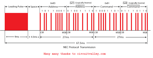
Now the question is how much time should be selected . We will use NEC Protocol's data type.You can use your own . Generally most of devices are using NEC Protocol. In NEC Protocol data contains 


[ start signal + 8bit Address+ Reverse 8bit Address+ 8 bit Command + Reverse 8bitCommand ]
Start Signal : 9 ms ON and 4.5 ms OFF 
(You can use as your wish but should be grater than bit's pulse)

Logical 1: 562 us ON and 16875 us OFF
Logical 0: 562 us ON and 562 us OFF


In this tutorial, we will use 4 bit data signal and we will use only data type .Our signal will be like this .


  Start + (reverse 4 bit command 4 bit command Combination total 8bit) + End


Receiver Unit's Working

I took this from http://learn.sparkfun.com
When IR-Led turns OFF or no signal comes to IR-Receiver, IR-Receiver provides 5v or high output to microcontroller's external interrupt pin .When IR-Transmitter turns ON, IR-Receiver provides 0v or low.
IR (Infrared) Remote Control Communication Between Two Microcontroller -Step By Step Tutorial : Part-1
IR (Infrared) Remote Control Communication Between Two Microcontroller

Transmitter unit sends Start Signal 9 ms ON and 4.5 ms OFF consequently IR-Receiver provides 9 ms OFF(0v) and 4.5 ms ON(5v)
After finishing this stage when first bit is sent, transmitter sends out pulse  562us ON and 562us OFF and consequently IR-Receiver provides 562us ON(5v) and 562us OFF(0v) . That will make external interrupts on microcontroller and timer0 will start to count duration of time so that each bit can be uniquely identified .In this way all bit's comes to the receiver unit . Finally we need to get our microcontroller understand about ending of signal and we send last signal pulse .

So First we need Interrupt to ditect signal .
Secondly , we need timer to measure time duration of signal so that we can identify each bit from signal (0 or 1). We also need PWM (Pulse width Modulation).
Ain't getting any visitors!
Please Share and Bookmark posts.

Tags

: (1) 18F2550 (1) 36KHz (3) and (1) arduino (1) Based (1) battery (1) Bipolar (1) Blinking (1) blinks (1) Bluetooth (1) bluetooth device interfacing (1) bluetooth module (1) button (1) circuit (1) clock (1) control (1) crystal oscillator (3) Db9 (1) DC Motor (2) digital (2) Digital Voting Machine (1) digital voting machine using pic (1) display (2) DS1307 (1) electronic (1) embedded c programming tutorial (11) embedded c tutorial (11) experiment kit (4) external interrupt (4) flash (1) flashing (1) Gas Leakage detector (1) HC-06 (1) home (1) how (1) How to (10) i2c tutorial (1) in (1) indicator (1) infrared Connection (3) interface (8) interfacing (3) Interrupt (3) Introduction (1) IR Connection (3) IR Receiver (4) IR Transmitter (4) key pad (1) keyboard (1) keypad (1) lavel (1) Lcd 16x2 (2) lcd 2x16 (2) led (1) lm35 (2) LPG (1) machine (1) make (1) Make bootloader (1) making (1) matrix (1) max232 (1) membrane keyboard (2) meter (2) Micocontroller (1) microchip (4) microchip pic (2) microchips (3) microcontroller (9) microcontroller based (3) microcontroller programming (3) Microcontroller Project (4) Microcontroller Projects (1) microcontroller_project (2) microcontrollers (4) Microprocessor (2) mikroC (5) mikroc code to start and stopstart and stop dc motor (1) mikroc pro for pic (2) Motion detector (1) MQ-9 Gas Sensor (1) musical (1) NEC Protocol (4) pcb (5) PIC (3) pic controller (11) pic microcontroller (11) pic microcontroller tutorial (11) pic programming (1) pic programming in c (12) pic proteus (1) Pic Tutorial (12) pic18 (2) pic18f2550 (11) picmicrocontroller (4) picRFモジュール (1) PIR Motion Sensor (1) printed circuit board (1) proteus (6) pulse width modulation (1) push (1) push button (1) PWM (1) real (1) rf transmitter (3) Rs 232 (1) Rs232 (1) scroll (1) scrolling (1) Serial communication (1) Serial Connection (1) Serial Port (1) serial port rs232 (1) Servo Motembedded c programming tutorial (1) simulation (2) Soil Moisture Meter (1) speed control (1) step by step (7) step bystep (1) Stepper Motor (2) text (2) Thief Detector (1) time (1) timer (4) timer0 (4) tone (1) TSOP38236 Receiver (4) tutorial (2) Unipolar (1) USART Connection (1) USB (1) usb 1.0 (1) USB bootloadere (1) USB HID (1) using (9) voltmeter (1) voting (1) water level indicator (3) with (2) work (1)

Traffic Feed


Live Traffic Feed
Visitor Tracking

Leave Your Message Here

Name

Email *

Message *

Like on Facebook